Civil Black Box (Mastermind Community)
Wind Loads on Floor and Roof slabs?
The wind loads are applied only on the walls, how about floor slabs? will this not cause add-on effect to the sidewall pressures? Is it not required to consider in RCC structures? As this will have significant impact on Industrial or Wearhouse shelters.
Upload your Testimonials here!
Use the comment box to upload your Testimonials or create a new post to do the same.
Water absorption criteria of Clay Bricks - As per IS Code provisions
Determination of water absorption of Clay Bricks is carried out as per IS 3495 (Part-2) : 2019 "Burnt Clay Building Bricks- Methods of Tests (Part-2 Determination of Water Absorption)".
There are 02 methods of assessing the water absorption of Clay bricks which are given as under. Sampling of the clay bricks is done as per provisions mentioned in IS 5454 : 1978.
24-Hour Water Absorption Test
05-Hour Boiling water absorption test
Let's have a look at both these methods one by one.
(Method-1) 24-Hour Water Absorption Test
(a) Preconditioning of Brick Samples
-
Drying the Bricks
Dry the bricks in a ventilated oven at a temperature of 105 to 115°C for not less than 24 hours
To be dried until two successive weighings at intervals of 2 h show an increment of loss not greater than 0.2 %.
Cooling the Bricks to room temperature
Weighing the dried Bricks (M₁)
(b) Procedure of Water Absorption
-
Immersion in Water
Immerse the dried sample in clean distilled water at 15 to 30°C for 24 h.
Removing excess water by wiping the bricks with a damp cloth
Weighing the Bricks within 03 mins after removal from water (M₂)
(c) Calculation of water absorption

(Method-2) 05-Hour Boiling water absorption test
(a) Preconditioning of Brick Samples
Same as for the 24-Hour Water Absorption Test
(b) Procedure of Boiling Water Absorption
Immersion of the dried sample in clean distilled water at 15 to 30°C
Heat the water to boiling point within 01 hour & boil continuously for 5 hours
Allow the bricks to cool between 15 to 30°C by a natural loss of heat
Removing excess water by wiping the bricks with a damp cloth
Weighing the Bricks within 03 mins after removal from water (M₃)
(c) Calculation of water absorption

Water Absorption conditions as per IS 1077
Following is the condition for assessing whether the brick lot is to be passed or failed:

Reference IS Code with Download Link:
IS 3495 Part 2 2019.pdf 456.97 KB
---- The End ----
Let me know if you liked the article. Your feedback matters a lot.
Have a wonderful day!
Kushal @ Civil Black Box
Sampling of the clay bricks - As per IS Code provisions

Sampling is carried out as per
IS 5454_1978_Reff2020.pdf 368.45 KB
Lot: LOT is a collection of bricks of the same class and size, manufactured under relatively similar conditions of production. For the purpose of sampling, a lot shall contain a maximum of 50 000 bricks
Philosophy of Sample Collection
Random Sampling: Collecting samples at random from different stacks
Stratified Sampling: Dividing the stacks into strata or sections and collecting samples randomly from each so that a true sample set is collected (As per IS 4905: 2005 (Reaffirmed 2020))
Sample Collection Methods
Sampling in motion: Collecting samples randomly when bricks are being moved
Sampling from Stack: Collecting samples from existing stacks by dividing the stack into imaginary sections and selecting randomly
Sampling from trucks and lorries: Collecting samples randomly from different trucks or lorries.
Sample Collection for different characteristics:
1. Sampling for visual & dimensional characteristics
Individual brick characteristics like shape & edges
Dimensions of Bricks checked for 20 bricks and averaging the results

2. Sampling for physical characteristics
Following physical parameters are checked with the sample set:
Compressive Strength of Clay Bricks
Water absorption criteria of Clay Bricks
Efflorescence in Clay Bricks

---- The End ----
Did you like the article? Please let me know.
Have a wonderful day!
Kushal @ Civil Black Box
Efflorescence in Clay Bricks - As per IS Code Provisions

The examination of the degree of Efflorescence in clay bricks is done as per
IS 3495 Part 3 2019.pdf 464.87 KB
.
Method of Efflorescence Test:
Sampling of the clay bricks
Removing any dirt on the brick surface that may be confused as efflorescence using a soft bristle brush
Placing the bricks (sample set) UPRIGHT (with the longer side of the brick as vertical) in the dish containing Distilled Water
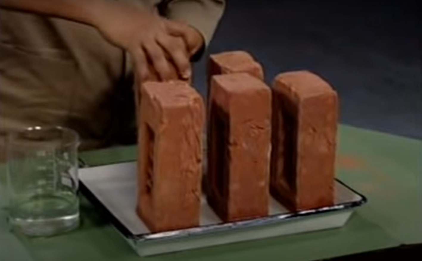
The depth of water should be 25 mm
The dish with water and bricks should be placed in a warm room with a temperature of around 25-30° C
Allow the entire water to evaporate
Once the water is evaporated, fill up the dish once more with 25mm of water
All the entire water to evaporate once more as before
Classification of Efflorescence
Once the test is concluded as per the above method, the bricks are examined and classified as under:
Nil — When there is no perceptible deposit of efflorescence.
SIight — When not more than 10 percent of the exposed area of the brick is covered with a thin deposit of salts.
Moderate — When there is a heavier deposit than under ‘slight’ and covering up to 50 percent of the exposed area of the brick surface but unaccompanied by powdering or flaking of the surface.
Heavy — When there is a heavy deposit of salts covering 50 percent or more of the exposed area of the brick surface but unaccompanied by powdering or flaking of the surface.
Serious — When there is a heavy deposit of salts accompanied by powdering and/or flaking of the exposed surfaces.
Acceptance Criteria of Bricks for the degree of Efflorescence:
Clay bricks are only accepted for use as per the following criteria:

---- The End ----
Let me know if you liked the article above.
Have a wonderful day,
Kushal @ Civil Black Box
Compressive Strength of Red Clay Bricks - As per IS Code provisions
Compressive strength of clay bricks is carried out as per
IS 3495 Part 1 2019.pdf 456.53 KB
.
Method of testing the bricks involves the following sequence:
1. Immersion of Bricks
Immerse the brick specimens in water at a temperature of 27 ± 2°C for 24 h.
Remove the specimens and drain out any surplus moisture.
2. Grinding the surface
Remove unevenness observed in the bed faces to provide two smooth and parallel faces by grinding.
However, If the grinding process is expected to significantly alter the contact area of the tested faces then the capping shall be done using cement mortar to achieve two smooth and parallel faces.
3. Filling of Frog with Mortar
Use a cement/sand mortar for capping and filling the frog (where provided) and all voids in the bed faces
Store under the damp jute bags for 24 h followed by immersion in clean water for 3 days at a temperature of 27 ± 2°C. Remove, and wipe out any traces of moisture.
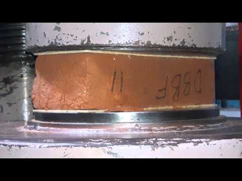
4. Procedure for Testing
Place the specimens with flat faces horizontal, and mortar filled face facing upwards between two 3-ply plywood sheets each of 3 mm thickness and carefully centered between plates of the testing machine.
Apply load axially at a uniform rate of 7 ± 1 N/mm2/min till failure occurs and note the maximum load at failure.
5. Compressive Strength Calculation

Failure/ Pass Criteria for Compressive Strength
A lot of brick shall be considered to be defective / failed if any of the following conditions are met:
Average compressive strength of samples as Sampling Criteria should not be less than class strength of the bricks.
Any individual brick strength comes out to be less than 15% of Class Strength
For example, a brick lot may be examined for approval or denial as per follows:
For Bricks of Class-10, the average compressive strength of say a sample size of 10 bricks for a lot size of 30000 bricks shall not be below 10 N/mm²
Of the 10 bricks tested above, the compressive strength of none of those bricks should fall below 15% of class strength of 10 N/mm² i.e. 8.5 N/mm²
Originally the criteria of failure was 20% as per IS 5454 Clause 5.2.1.1, however, as per the amendment issued in 2008 for IS 1077 the criteria for failure has been made more stringent by reducing it from 20% to 15%.
---- The End ----
Please let me know if you liked the article and suggest improvements if any.
Have a wonderful day,
Kushal @ Civil Black Box
Red Clay Bricks - Everything You Need To Know (as per IS Code Provisions)

Brickwork is one of the most widely used Building Materials when it comes to simple and semi-advanced construction in India. Although used for non-structural members the specifications of clay bricks play an important role in the entire construction philosophy.
The IS code which talks about the Red Clay Bricks is IS 1077 1992 (Reaffirmed 2016) "Common Burnt Clay Building Bricks- Specifications".
Classification of Bricks
Classification of Bricks is done by Designating a Class to the bricks.
Brick of Class 7.5 means that the compressive strength of the brick is 7.5 N/mm².

Characteristics of Clay Bricks
There are two categories in which clay bricks are characterized for examination:
Visual Characteristics
Physical Characteristics
1. Visual Characteristics
Dimensions of Bricks
There are two sizes of bricks as per the IS code:
(a) Modular Size of Bricks

(b) Non-modular size of Bricks

Tolerance for checking Dimensions
Tolerance is checked by calculating the total dimensions of Length, Width, and Height of 20 Bricks laid in sequence along the length, width & height.
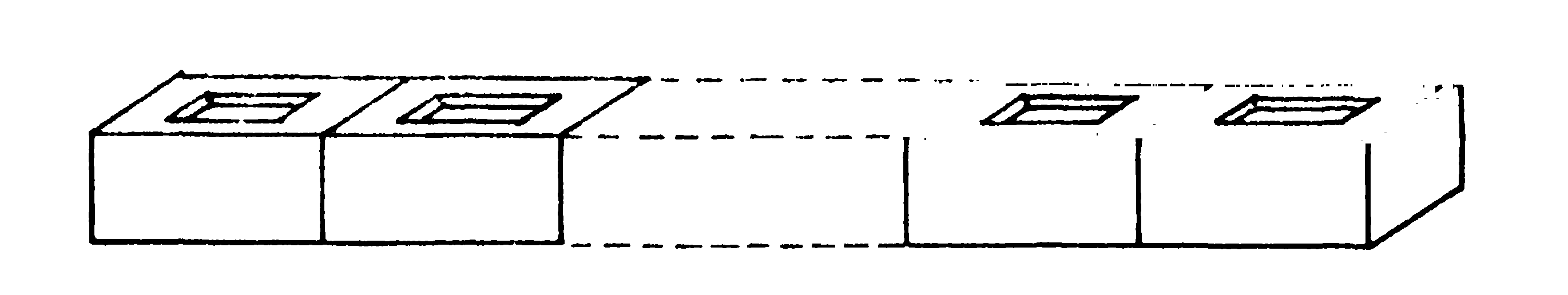
Tolerance is checked as per the conditions given in the table below:

2. Physical Characteristics
(a) Compressive Strength
Compressive Strength of Clay Bricks is calculated as per the guidelines laid down in IS 3495 (Part-1): 2019
Average compressive strength of samples as per Sampling Criteria should not be less than class strength of the bricks.
Any individual brick strength comes out to be less than 15% of Class Strength.
Originally the criteria of failure was 20% as per IS 5454 Clause 5.2.1.1, however, as per the Amendment issued in 2008 for IS 1077 the criteria for failure has been made more stringent by reducing it from 20% to 15%.
(b) Water Absorption
Bricks are tested for their Water absorption criteria of Bricks characteristics
Testing is as per IS 3495 ( Part 2) : 2019
Bricks are immersed in cold water for 24 hours

(c) Efflorescence
Bricks are tested for efflorescence properties as well
Testing is as per IS 3495 (Part-3) : 2019

Relevant IS Codes with Download Links:
Ammendment 2008 IS 1077.pdf 15.36 KB
IS 3495 Part 1 2019.pdf 456.53 KB
IS 3495 Part 2 2019.pdf 456.97 KB
IS 3495 Part 3 2019.pdf 464.87 KB
IS 5454_1978_Reff2020.pdf 368.45 KB
----- The End -----
Let me know whether you liked the article or it needs further improvement.
Have a great day!
Kushal @ Civil Black Box
SFD BMD and Reactions in a Cantilever beam with Point load
Check out this YouTube Video for in-depth knowledge: https://youtu.be/lqzCe0gXoiw

Shear Force Diagram (SFD) and Bending Moment Diagram (BMD) play a crucial role in designing any structure. The essence of SFD and BMD lies in the fact that they translate the external force system into an internal force system. These internal forces are then translated to Internal Stresses. Finally, the internal stresses may be compared with the strength of the material to evaluate whether the structure is safe or not.
The cantilever beam is a beam supported on one end by fixed support. This fixed support offers complete rigidity by producing 03 reactions in the form of Vertical force reaction, Horizontal Force reaction, and Moment reaction.
In a beam system, however, we consider the force system to be Coplanar-Parallel i.e. there is no component of external force in the Horizontal axis direction. This reduces the reactions to 02 in number.
Solving any beam is a simple 04 step process:
Finding the Degree of Structural Indeterminacy
In order to find the Degree of Structural Indeterminacy, you can check out my previous video on the topic here: https://youtu.be/acx_55ZcpZg In the case of a cantilever beam, the Degree of Indeterminacy is Zero. Hence, the structure is Determinate and hence all the reactions and internal forces can be evaluated by just using the equations of static equilibrium
Free Body Diagram
Free Body diagram is a diagram of the structure wherein all the supports have been replaced by an unknown reaction force. FBD is hence a schematic display of the structure where only the forces on the structure are shown and no supports or restraints.
Finding the Reactions
Reactions for a cantilever beam can be simply evaluated by using the equations of Static Equilibrium. The Free Body Diagram is checked for equilibrium for No vertical, horizontal, or rotational movement. This is achieved by equating the Summation of all forces in the X direction and Y Direction as zero as well as all moments about the XY plane or Z direction as zero
Finding Shear Forces and Shear Force Diagram (SFD) & Bending Moments and Bending Moment Diagram (BMD)
Shear force and bending moments inside the body are obtained by cutting a section at a distance of x from either side and exposing the internal unknown forces in the form of Horizontal and Vertical force as well as Moment. These sections are again passed through the framework of static equilibrium and internal forces are calculated as a function of x. This is later used to find the Shear Force Diagram (SFD) and Bending Moment Diagram (BMD)
Check out this YouTube Video for in-depth knowledge: https://youtu.be/lqzCe0gXoiw
Thanks,
Kushal
Determinate Vs Indeterminate Structures | Finding the degree of Indeterminacy
Get the in-depth knowledge from the YouTube Video: https://youtu.be/acx_55ZcpZg

A Structural Engineer's journey starts with 2D structural analysis. The current scenario of Structural consultancy is almost entirely governed by the use of Structural Analysis Software like STAAD Pro or ETABS for analysis and design of structures.
Why then do we need to go through the pain of manual calculations of 2D structures when in fact we almost never deal with 2-dimensional structures in real life nor do we almost ever use manual calculations for analysis and design?
This is similar to asking whether we need the knowledge of plus or minus operators or what it does in maths to truly use the calculator. And you must have guessed it, the basic knowledge is most definitely required.
As I keep repeating over and over again when it comes to the use of any Software "Garbage In, Garbage Out!". The software can only do what the user asks it to. It doesn't have any analytical brain of its own. That is where we humans come into the picture. We tell the software what we want of it and we let the software run calculations to fetch us desired results.
Like every field of learning, basics are the key to mastery. Tools are just that, tools. You are the brain of the operation. In structural analysis, the journey truly begins by understanding the determinacy of structures.
Statical determinacy or indeterminacy of any structure plays a crucial role in our ability to solve the structure easily. For a statically determinate structure, the entire structure can be effectively analyzed using just the equations of statical equilibrium.
Statically determinate and indeterminate structures are differentiated using these 03 criteria which are based upon:
Whether a structure can be completely analyzed by just the equations of equilibrium
Determinate Structures - Structure that CAN be fully analyzed using just the equations of static equilibrium
Indeterminate Structures - Structure that CANNOT be fully analyzed using just the equations of static equilibriumWhether internal stresses can be developed without an external force such as due to temperature variation and lack of fit.
Determinate Structures - Structure that CANNOT develop internal stresses due to temperature variation or lack of fit
Indeterminate Structures - Structure that CAN develop internal stresses due to temperature variation or lack of fitWhether the Internal Forces (Shear Force, Bending Moment, etc.) depend on the material i.e. Type of Material or area of cross-section of the body
Determinate Structures - Structures whose internal forces are INDEPENDENT of Material properties
Indeterminate Structures - Structures whose internal forces are DEPENDENT on Material properties
The above 03 criteria will help you determine the determinacy of the structures. Structures however are divided into 03 categories again:
-
Beams
These are structures subjected to transverse loads only
Based upon Coplanar Parallel Force System
The structure is termed completely solved when Shear Force Diagram & Bending Moment Diagram is known
Total equations of static equilibrium is 02 i.e. Sum of Fy and Mz is Zero
-
Frames
These are structures subjected to lateral & transverse loads only
Members connected by rigid joints
Based upon Coplanar Force System
The structure is termed completely solved when Shear Force Diagram, Axial Force Diagram & Bending Moment Diagram is known
Total equations of static equilibrium is 03 i.e. Sum of Fx, Fy and Mz is Zero
-
Truss
Members in such a structure are connected by Pinned Joints only
Hence, members are subjected to Axial forces only
No Shear forces or Bending is generated in the structural members
The structure is termed completely solved when Axial Forces in each member are known
Total equations of static equilibrium "for each joint" is 03 i.e. Sum of Fx, Fy and Mz is Zero
Knowledge of whether a structure is determinate or indeterminate is not enough. We need to further investigate the degree of indeterminacy which is calculated by using a simple equation:
Degree of Indeterminacy = Unknown Forces - Equations of Equilibrium
Degree of Indeterminacy is also known as Structural redundancy
Unknown Forces are Reactions
If, Degree of Indeterminacy = 0, the structure is Determinate
If, Degree of Indeterminacy > 0, the structure is Indeterminate
For different types of structures the equations can be modified as follows:
Beams
Equations of Equilibrium = 2
Degree of Indeterminacy = Reactions - 2Frames
Equations of Equilibrium = 3
Degree of Indeterminacy = Reactions - 3Truss
Equations of Equilibrium (each joint) = 2
Total Equations of Equilibrium = 2j
Unknowns = Reactions + Each Member Axial Force = R + m
Degree of Indeterminacy = Internal DOI + External DOI
Internal DOI = m - (2j - 3)
External DOI = R -3
Knowledge of the degree of Indeterminacy is very crucial in manual calculations of the structure since it provides the total redundancy of the structure. this tells us how many additional equations are necessary to fully analyze the structure.
For in-depth knowledge on the subject check out the YouTube Video: https://youtu.be/acx_55ZcpZg
Thanks,
Kushal
PS: Please share the video with your friend and colleagues to help us out!
How is Load Transferred from Slabs, Beams & Columns to Foundation?
Check out the video for an in-depth understanding of the topic: https://youtu.be/cU0uUE0Z32E
Loads on a structure are ultimately passed on to the soil underneath. Let's assume that the soil or earth beneath the structure is strong enough to absorb the load without failure. In such cases, understanding what goes on above the ground and inside the structure is key.
Any structure is composed of members. If we consider a Reinforced Concrete Structure (RCC) the component structural members are usually slabs, beams, and columns.
In such a case having an understanding of how the loads are transferred from the top of the structure to the bottom of the structure is one of the best skills you can acquire as a structural consultant or engineer.
In a single-story RCC frame structure, the load starts to flow from the slabs onto the supporting beams.
This load on the beams is then transferred onto the columns supporting the beams.
From thereon the load moves down to the supports where it is eventually supported by the soil.
This seems simple enough to understand. But the true understanding comes from realizing how the loads from slabs are distributed to the beams. Usually, the load on a slab is divided by the 45-degree rule. If we have a square slab the load is divided into 04 equal triangles with each beam taking up the triangular load.
If we replace the square slab with a rectangular slab the load distribution changes slightly. Now the shorter beam takes the triangular part of the slab load and the longer side takes a trapezoidal portion of the load (again using the 45-degree distribution pattern).
Beams are relatively straightforward to solve for the transference of loads. The key point here is that each beam is only taking the combination of loads from the adjacent slabs and nothing from the floor above it. The same goes for slabs. Slabs usually resist only the load on themselves. The beams take the load of adjacent slabs.
The tricky part is the column. A column takes up the loads transferred on to it from the beams it supports. However, unlike slabs that support loads on themselves and beams that support loads from adjacent slabs on the same level, a column takes up the CUMULATIVE load from the beams above it and from the columns above it.
Hence, a column at the top floor would be supporting only the loads from the beams at the top floor. However, a column at the bottom-most floor would be supporting not only the loads from the beams at that level but also all the column loads above right from the top floor downwards.
Check out the video for an in-depth understanding of the topic: https://youtu.be/cU0uUE0Z32E
Thanks,
Kushal
PS: Please support our work by sharing the YouTube Channel & Videos with your friends and colleagues
@Bartholomew Appiah Thank you so so much for your kind words of appreciation. Thank you for taking the time to record the testimonial. And thank you for being a part of the Civil Black Box. Seeing messages and videos like this is what matters the most to me. I am really happy that you have been able to learn and enjoy the lectures. I hope we would meet someday in real life too. Have a wonderful career ahead. Thank you once again. 🙏